


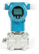
Capacitive transmitter


Model name
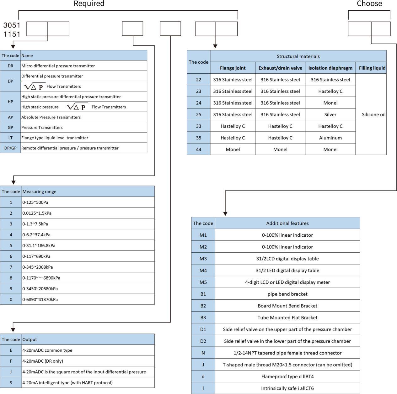
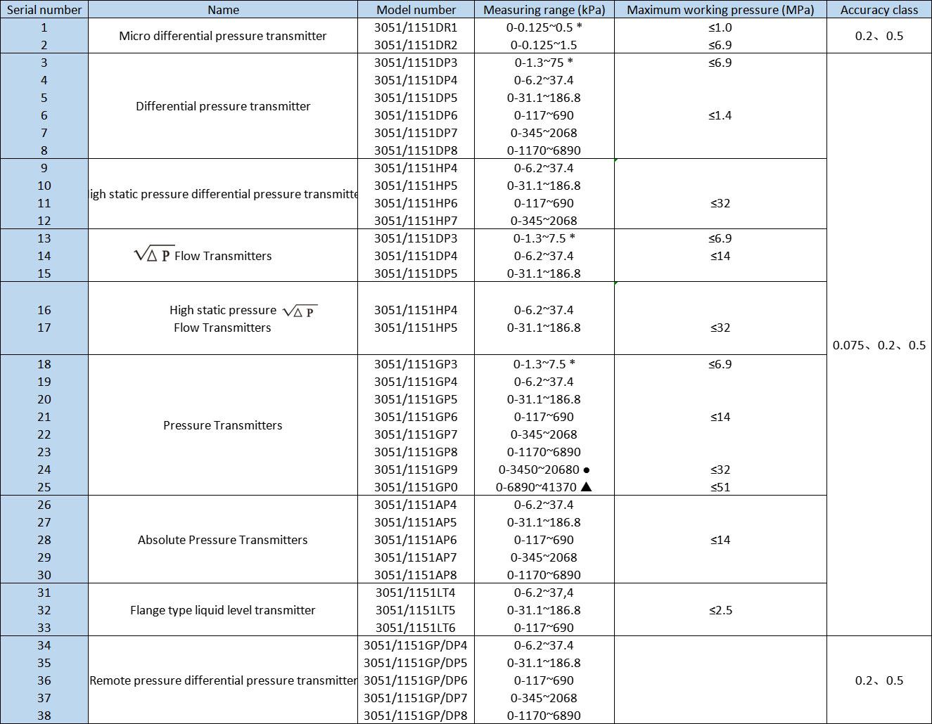
Product specification
Main features
◆Complete variety, high precision, good stability, cheaper price than similar imported instruments;
◆Span and zero position can be continuously adjusted externally;
◆Positive migration up to 500%, negative migration up to 600% (minimum range);
◆Adjustable damping;
It can be seen from Table 1 that the 3051/1151 series capacitive transmitters produced by our company are complete in variety, and users can choose them arbitrarily according to different needs. In addition to 361L stainless steel, the wetted material also has Hastelloy C, Monel, SIOCFLON coating, etc., which can be used to measure corrosive media.
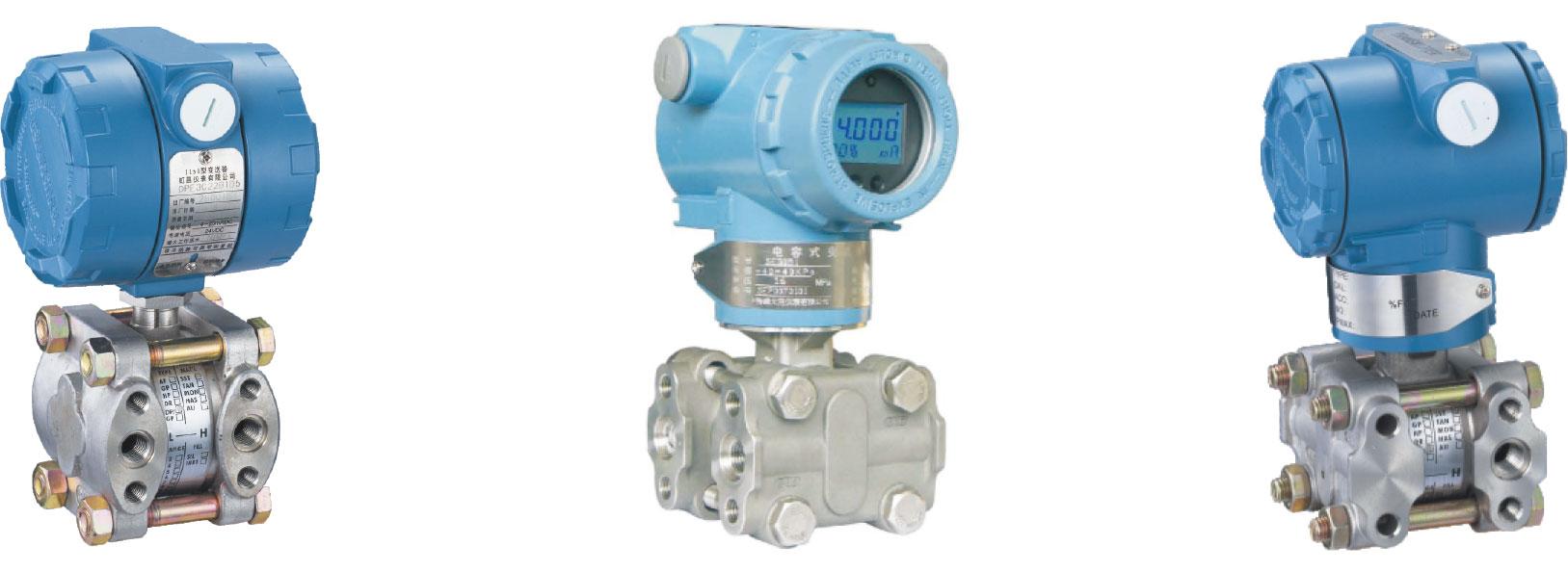
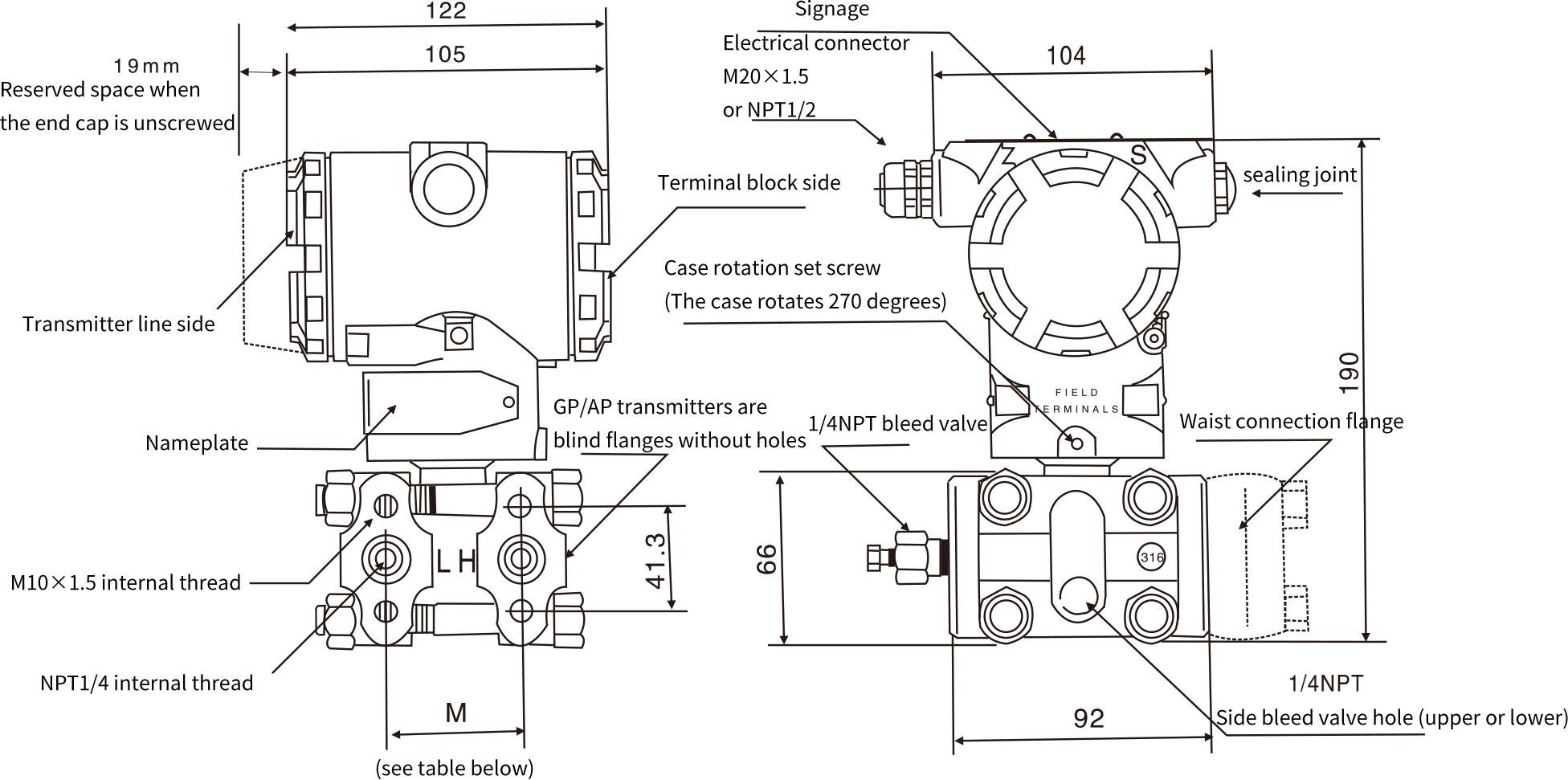
The 3051-1151 series transmitters are compact in design, easy to install, use and adjust. The electrical enclosure adopts a two-cavity structure, that is, the terminal block and the amplifier circuit each occupy a cavity. The airtightness is good, and it has an explosion-proof and all-weather structure. The amplifier circuit has reverse polarity protection to prevent damage to the transmitter due to wrong connection of power supply polarity. Since the volume change of the transmitter is less than 0.16cm3 when it is working, there is no need to add a condenser or liquid level cylinder to compensate for the volume change.
The 3051/1151 series transmitters produced by our company can be equipped with a 0~100% linear indicator for on-site output indication; they can also be equipped with a digital display for on-site output display. The display is 31/2 times LCD or LED display, and the reading accuracy ± 0.5% + 1 word, because the A/D converter, amplifier, liquid crystal, etc. of the display all use high-quality devices, so it is accurate, durable and reliable. Users can choose according to their own habits.
Working principle
The two pressures of the measured medium enter the high and low pressure chambers, act on the two isolation diaphragms of the 6-element (ie, the sensitive element), and transmit to the pre-tensioned measuring membrane through the isolation diaphragm and the filling liquid in the 6-element both sides of the slice. The measuring diaphragm and the electrodes on the insulators on both sides form a capacitor respectively. When there is no pressure or the pressure on both sides is equal, the measuring diaphragm is in the middle position, and the capacitances of the two capacitors on both sides are equal. When the pressure on both sides is not consistent, the measuring diaphragm is displaced, and the displacement is proportional to the pressure difference, so the capacitance on both sides is not equal. By detecting the differential capacitance on the capacitor plate, the differential capacitance is detected by the electronic circuit. The capacitance is converted and amplified into a two-wire current signal of 4-20mADC. The working principle of pressure transmitter and absolute pressure transmitter is the same as that of differential pressure transmitter, the difference is that the pressure of the low pressure chamber is atmospheric pressure or vacuum.
|
Range code |
1、2、3、4、5 |
6 |
7 |
8 |
9 |
0 |
|
M |
54 |
55.2 |
55.6 |
57.2 |
59 |
60.6 |
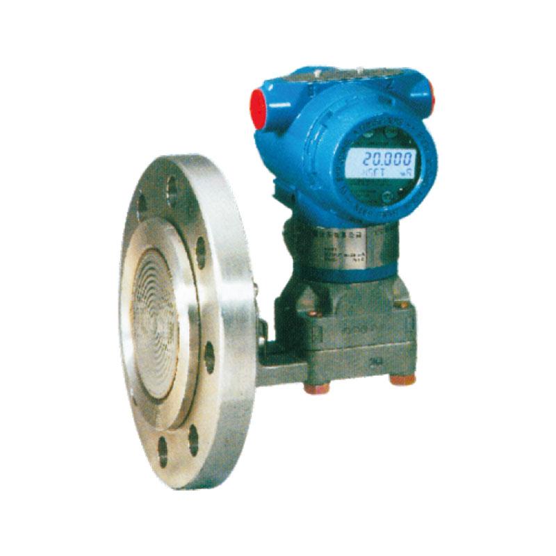
Overview
The installation flange standard of 3051/1151TL capacitive liquid level transmitter is ANSI 2", 3", 4", and the flange level is 150lb and 300lb. The flange installation size is shown in the chart below. Standard, DN=80, 100, PN=2Mpa. The material of the liquid diaphragm includes 316L, Hastelloy C-276, Monel, silver, etc. The company can also provide users with other special specification installation flanges. Users do not pay attention Tomorrow, our company will supply with 3"150lb (2.5Mpa) installation flange.
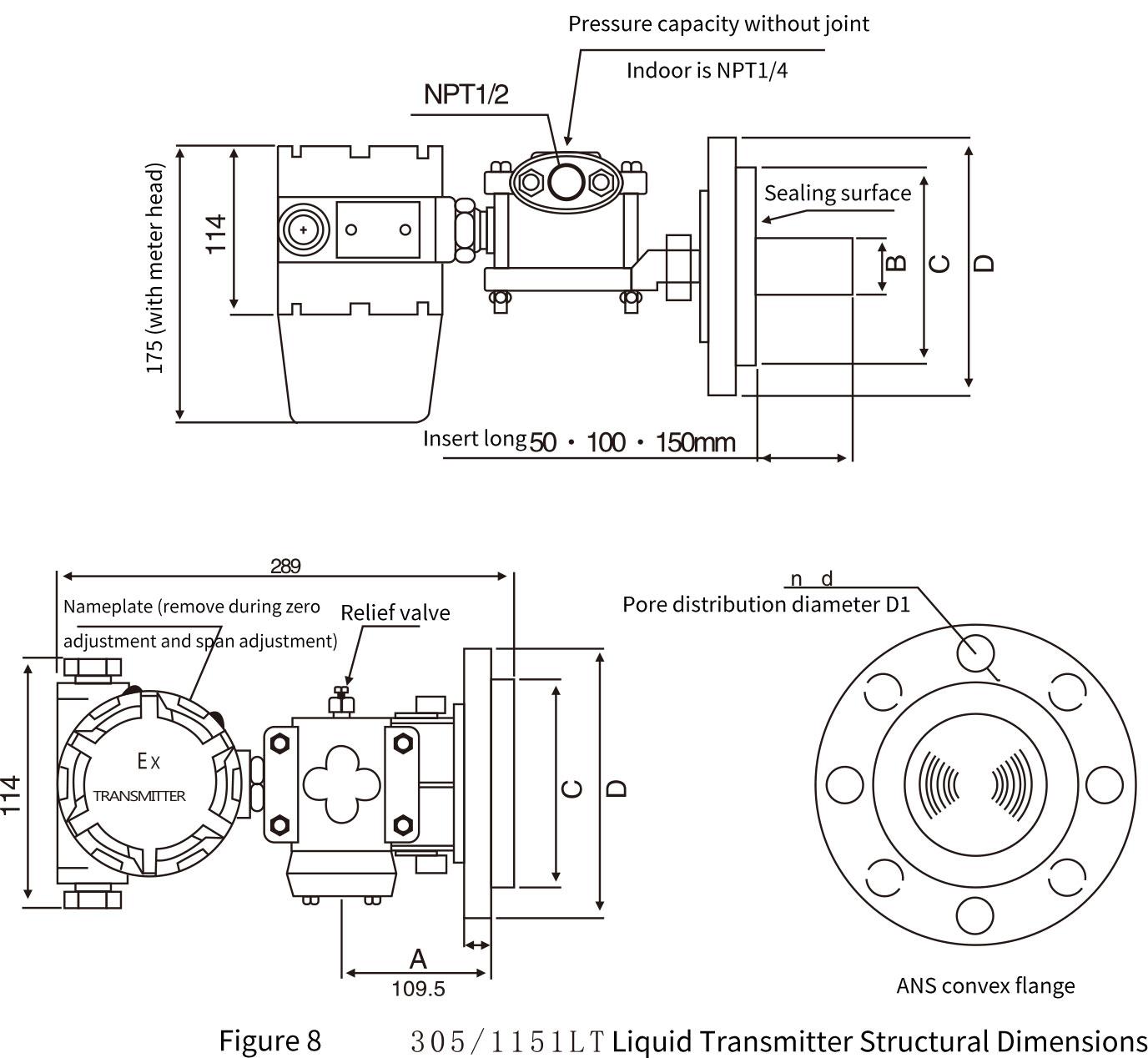
D, D1, n, d, A, B, C dimensions in the above figure
|
Flange size mm |
Bolt hole |
||||||
|
Standard flange size |
Outer diameter D |
Thickness A |
B |
C |
Number n |
diameter d(mm) |
Distribution diameter D1(mm) |
|
2" |
152 |
23 |
60 |
98 |
4 |
19 |
120 |
|
3" |
190 |
24 |
66 |
127 |
4 |
19 |
152 |
|
4" |
229 |
24 |
89 |
157 |
8 |
19 |
191 |
Product Selection Table
|
Model code |
Function Description |
||||||
|
DWP-3051/1151LT |
Flange type liquid level transmitter (maximum working pressure 2.5MPa; special 4MPa—please specify when ordering) | ||||||
|
Measuring range |
4 |
|
|
|
0-6.2~37.4 kPa | ||
|
5 |
|
|
|
0-31.1~186.8 | |||
|
6 |
|
|
|
0-117~690 | |||
|
Output |
|
E |
|
|
|
4-20mADC common type, adjustable damping | |
| S |
|
|
|
4-20mADC intelligent type with HART protocol | |||
|
Connection form (or category) |
|
|
|
Flat flange EO(2"), A0 (3"), B0(4") | |||
|
2′′ |
|
|
Access flange: E2, E4, E6, (the length of the insertion tube is 50, 100, 150mn respectively) | ||||
|
3′′ |
|
|
Plug-in flange: A2, A4, A6, (insert lengths are 50, 100, 150mm respectively) | ||||
|
4′′ |
|
|
Plug-in flange: B2, B4, B6, (insert lengths are 50, 100, 150mn respectively) | ||||
|
Structural materials |
|
|
Low pressure side pressure chamber and liquid contact diaphragm |
High pressure side liquid isolation diaphragm |
|||
|
22 |
|
316 |
316L |
||||
|
23 |
|
316 |
Hastelloy C |
||||
|
24 |
|
316 |
Monel |
||||
|
25 |
|
316 |
Tantalum |
||||
|
33 |
|
Hastelloy C |
Hastelloy C |
||||
|
35 |
|
Hastelloy C and Tantalum |
Tantalum |
||||
|
44 |
|
Monel |
Monel |
||||
|
Additional features |
M1 |
0-100% linear indicator | |||||
|
M3 |
3 1/2LCD digital display | ||||||
|
M4 |
3 1/2 LED digital display | ||||||
|
M5 |
4-digit LCD or LED digital display | ||||||
|
B1 |
Pipe bend bracket | ||||||
|
B2 |
Board Mount Bend Bracket | ||||||
|
B3 |
Tube Mounted Flat Bracket | ||||||
|
D1 |
Side relief valve on the upper part of the pressure chamber | ||||||
|
D2 |
Side relief valve in the lower part of the pressure chamber | ||||||
|
N |
Low pressure side 1/2-14NPT tapered pipe female twisted joint | ||||||
|
J |
Low-pressure side M20×1.5 T-shaped male thread sand connection | ||||||
|
d |
dllBT4 | ||||||
|
i |
Intrinsically safe iallCT6 | ||||||
|
DWP-1151LT5EA622M3B1 ---Type selection example |
|||||||
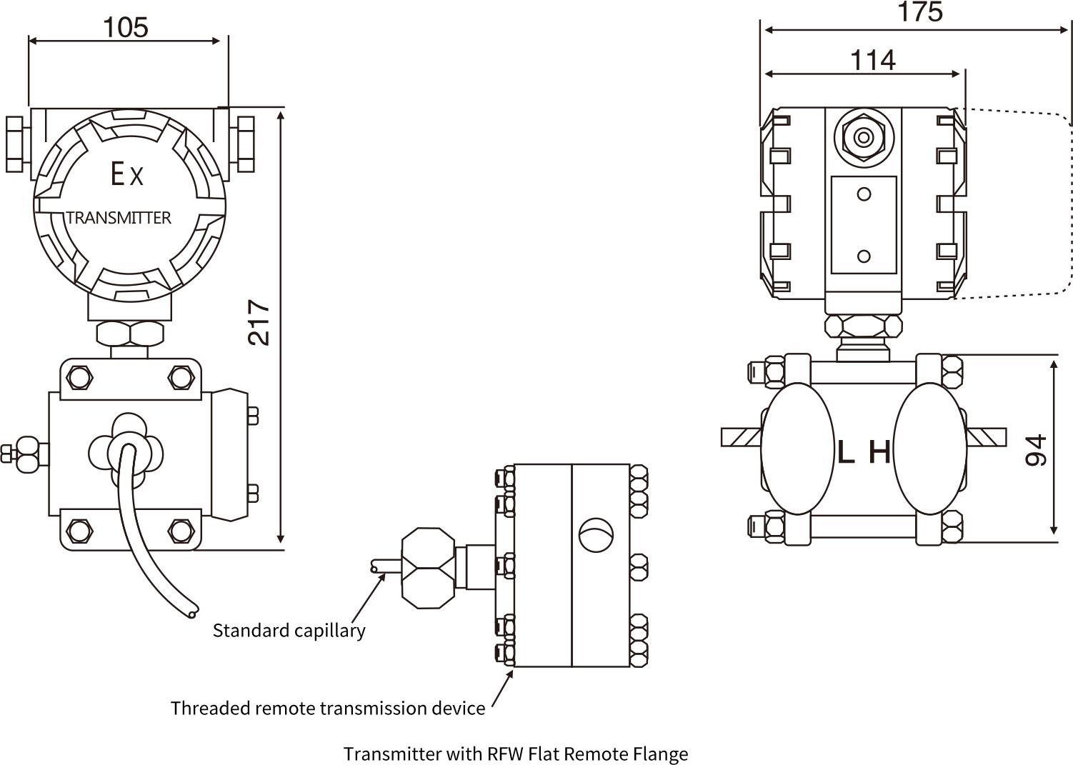
Overview
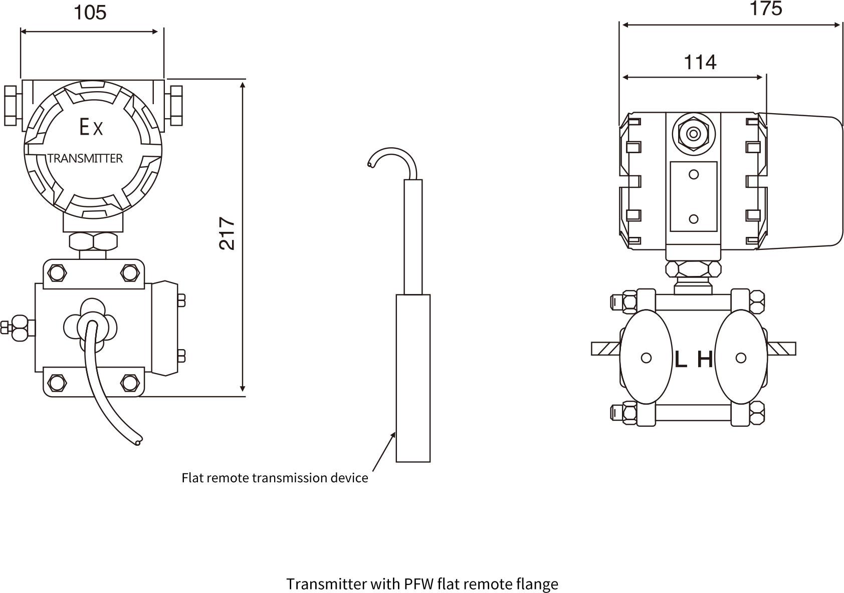
The 3051/1151DP·GP transmitter becomes a remote differential pressure or pressure transmitter after being equipped with a remote sealing device. The remote transmitter can avoid direct contact between the measured medium and the diaphragm of the transmitter.
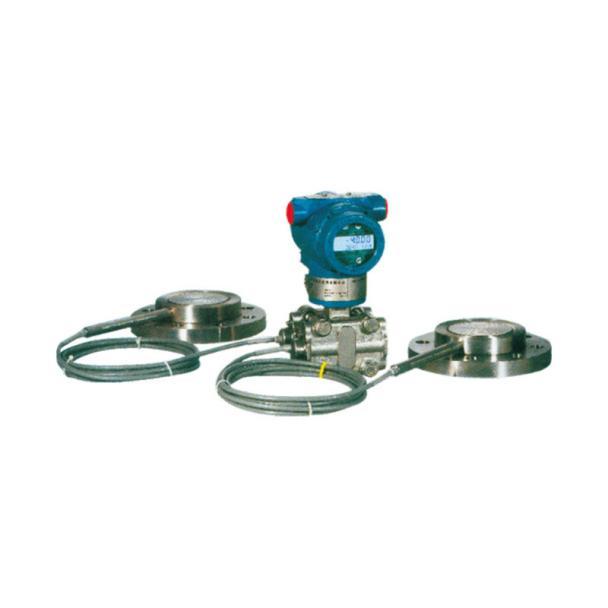
Applicable environment
1. The measured medium has a corrosive effect on the transmitter joint and sensitive components;
2. It is necessary to isolate the high-temperature measured medium from the transmitter;
3. There are solid suspended matter or high viscosity in the measured medium, which is easy to block the transmitter joint and pressure chamber;
4. Hygienic conditions must be protected to prevent contamination.
Measuring range: 0~6kPa-0~10Mpa
A variety of structural materials are provided, and the welding structure of the components of the remote transmission device is highly reliable. The low-volume design of the liquid-filled cavity reduces the impact of temperature. According to user requirements, the operating temperature range of ordinary silicone oil is -40+149°C; the operating temperature range of high-temperature silicone oil is 15-315°C, see Table 23 for details.
The upper limit of the working pressure of the remote transmission device is the rated value of the remote transmission device selected by the user; the working pressure shall not be lower than 3.5kPa (absolute pressure). For corrosive media, please refer to Table 25 for the material selection of the isolation diaphragm (only for reference when selecting by the user).
|
Model code |
Function Description | ||||||
|
3051/1151DP -GP |
Remote differential pressure, pressure transmitter | ||||||
|
Measuring range |
4 |
|
|
|
|||
|
5 |
|
|
|
||||
|
6 |
|
|
|
||||
|
7 |
|
|
|
||||
|
8 |
|
|
|
||||
|
Output |
|
E |
|
|
|
||
| S |
|
|
|
||||
|
Flange material |
|
|
|
Flange material |
Isolation diaphragm |
||
|
12 |
|
|
Carbon steel nickel plated |
316L stainless steel |
|||
|
22 |
|
|
316 stainless steel |
316L stainless steel |
|||
|
Isolation diaphragm |
s1 |
|
One remote devices |
According to Table 16~21 to place an order |
|||
|
s2 |
|
Two remote devices |
|||||
|
Additional features |
M1 |
0~100% linear indicator | |||||
|
M3 |
3 1/2LCD digital display | ||||||
|
M4 |
3 1/2 LED digital display | ||||||
|
M5 |
4-digit LCD or LED digital display | ||||||
|
B1 |
Pipe bend bracket | ||||||
|
B2 |
Board mount bracket | ||||||
|
B3 |
Tube Mounted Flat Bracket | ||||||
|
d |
Flameproof dllBT4 | ||||||
|
i |
Intrinsically safe iall CT6 | ||||||
|
DWP-1191RFW21A11A21-30 ---Selection example |
|||||||
|
product name |
product model |
basic function |
remarks |
|
|
Capacacitive differential voltage transmitter |
TKWP-3051 Series |
 |
Measurement range: -100KPa-40MPa Measurement accuracy: 0.2% 0.5% 0.075%
Working power supply: DC12-36V Output signal: 4-20mA 0-10V 0-5V 1-5V |
Stainless steel belt base |