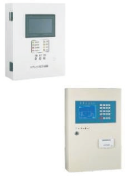
Electrical fire host computer

Overview
The electrical fire monitoring system is a computer measurement and control system that integrates alarm, monitoring, control and management functions, which is independently developed in response to the sharp increase in domestic electrical fires in recent years. The system has intuitive interface, strong usability, reasonable structure, high reliability, strong function and convenient maintenance.
The system can be widely used in the centralized management of power consumption and fire prevention in large shopping malls, living quarters, production bases, office buildings, shopping malls, hotels, and scattered equipment. The adoption of this system not only greatly improves the continuity of the power supply system, but also eliminates electrical fires in the bud, providing a guarantee for safe electricity use.
The electrical fire monitoring equipment is the core of the electrical fire monitoring system, which can display various working states of the monitored circuit in real time. When the system is abnormal (over-current, residual current, over-temperature, etc.), the monitoring equipment will send out sound and light alarm signals to remind the staff to pay attention; and it can also display and record the specific content.
The electrical fire monitoring equipment implements the national standard GB 14287.1-2014 “Electrical Fire Monitoring Equipment”.
The main technical parameters
The main technical parameters:
1. Power supply:
① Rated working voltage 220V AC
② Backup power supply: When the main power supply is undervoltage or power failure, the working time of the monitoring equipment should be maintained for ≥4h
2. Working method:
24 hours non-stop work
3. Communication method:
Optional: PB two bus communication, RS485, CAN, communication distance ≤ 2km, depending on site conditions.
4. Monitoring capacity:
There are four circuits in total, each with 64 monitoring units (detectors), which can be expanded up to 256 monitoring units (detectors), depending on the equipment specifications.
5. Monitoring and alarming items:
① Residual current fault (leakage): fault unit attribute (location, type)
② Current and voltage faults (overcurrent, overvoltage): Faulty unit attributes (location, type)
Monitoring alarm response time: ≤30s
Monitoring alarm sound pressure level (A-weighted): ≥70db/1m
Monitoring alarm light display: red LED
6. Fault alarm items:
① Main power undervoltage or power failure
② Backup power battery short-circuit open circuit
Fault alarm response time: ≤60s,
Monitoring alarm sound pressure level (A-weighted): ≥70db/1m
Monitoring alarm light display: yellow LED
7. Control output:
Local alarm output contact type: switch type, normally open contact, capacity 250V/5A
8. Self-inspection items:
① Indicator light inspection: monitor the host indicator light;
② Fault sound inspection: monitor the fault sound of the host;
③ Alarm sound check: monitor the host alarm sound;
④ Printer check: monitor the host printer;
Self-test takes ≤30s
9. Historical records:
① Alarm type: fault unit attributes, occurrence time; storage capacity > 1000 events;
② Alarm event query: all or filter by alarm type and address conditions;
③ Print: You can print the historical record information.
10. Operation classification:
① “View” level:
Monitor real-time status and query historical fault alarm records.
② “Operational” level:
Monitor real-time status, query historical records; perform setting operations for each unit.
11. Use environmental conditions
① Ambient temperature: -20℃~+40℃
② Relative humidity: 10%~90%
③ Altitude: no more than 3000m
④ Place of use: The monitoring equipment should be installed in a dedicated control room
Setting and working status description
When the electrical fire monitoring equipment is in normal operation, manual intervention is generally not required until there is an alarm or failure in the system. However, you should read this manual in detail when you run it for the first time, so as to set its parameters and ensure that it works in a normal monitoring state.
When the electrical fire monitoring equipment is working normally, the corresponding fault or alarm light should be off, and no fault or alarm sound will be issued, and the LCD screen will display the corresponding measured parameters. If there is a fault or alarm message, the corresponding fault or alarm light will light up, accompanied by a fault or alarm sound.
1.Device Panel Description
Outline drawing of electrical fire monitoring equipment:
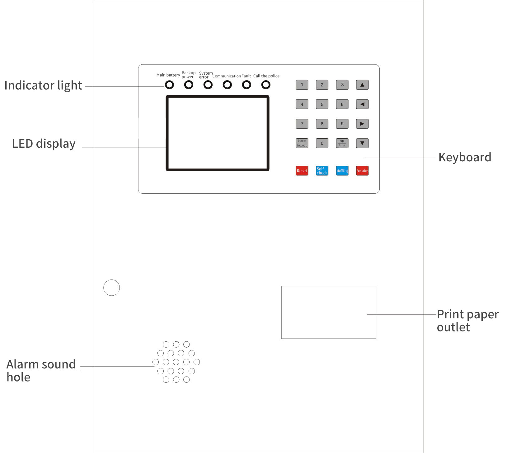
Host panel function description :
1) Display screen:
Display system status parameter information, man-machine dialogue function parts.
2) Indicator lights:
① Main power indicator: When the main power is normal, the electrical fire monitoring equipment is powered by the main power, and the main power indicator is always on in green
② Backup power indicator: When the main power is undervoltage or fails, the electrical fire monitoring equipment is powered by the backup power supply, and the backup power indicator is always on in green
③ System fault light: When the system fails internally (such as: the internal system cannot communicate, the line is disconnected, etc.), the system fault light is always on and turns yellow
④ Fault indicator light: When the system fails (such as: communication failure, power failure, etc.), the fault indicator light is always on in yellow, accompanied by an alarm sound
⑤ Alarm indicator light: When the controlled system has an alarm (such as: current alarm, residual current alarm, temperature alarm, etc.), the alarm indicator light is always on in red, accompanied by an alarm sound
3) Keyboard:
Complete the input function of man-machine dialogue, man-machine dialogue function parts.
4) Printer:
Provide printing of reports, status information, fault information, etc. (the system can be set to close)
5) Audio:
When the system is abnormal, the sound output device can send out distinctly different alarm sounds in case of alarm and failure.
2.Window display and setting instructions
There are seven grouping page windows in this monitoring device (can be manually switched by “Function” key):
1) Inspection window:
Display the current detector IP address, running status, and installation location. Use the “up and down” keys to control and view each detector. If there are many addresses, you can directly enter the three-digit address and it will automatically jump to the detector location (for example, enter 088 to be the detector with the 88th address). The addition of the installation location needs to be added through our company’s special software (any name can be up to 8 Chinese characters or 16 Arabic numerals or English).
2) Data window:
Display and view the value status of the detector under test, press the “up and down” key to view the value of the detector in sequence, or directly enter the three-digit address number to view.
3) Alarm window:
Press the “up and down” keys to display the historical information of the query alarm, or select a piece of information and press the “print” key to print.
4) Fault window:
Press the “up and down” keys to display the historical information of the query fault, or select a piece of information and press the “print” key to print.
5) Event window:
Press the “up and down” keys to display the history information of query faults and alarms, or select a piece of information and press the “print” key to print.
3) Setting window: (This window needs to be operated under the login status)
Press the “left and right” (left is up, right is down) to move to the detector option to select the address number, and then move to each parameter value, press the “up and down” button or directly enter the value to modify.
7) System window: (this window needs to be operated under the login status)
①Print management: set the printer to print automatically or manually, press the “left and right” (left is up, right is down) key to move to the print management position, then press the “up and down” key to select the printer status (1 is automatic, 0 is manual), then press “OK” to save the setting.
②System time: set the system time and date, press the “left and right” (left is up, right is down) key to move to the system time position, then press the “up and down” key to select the current time and date, and then press “OK ” key to save the setting.
③Factory backup and communication optimization: This function has nothing to do with the user.
④ System address: refers to the address of the monitoring device, which is used when connecting with multiple monitoring devices. A single monitoring device host does not need to be set up.
⑤ Adding devices: Press the “left and right” keys to move to the location of adding devices, then press the “up and down” or “OK” keys to add addresses one by one, or you can directly press the number keys to enter the number of addresses (such as typing 088, that is, 88 detectors address), and then press the “OK” key to confirm. The address added by the device must be consistent with the number of detector addresses on site, otherwise a fault will occur. Detector addresses can only be added and cannot be reduced. If you want to reduce, you must first delete all detector addresses (delete device option) and then add them.
⑥ Delete device: If you want to delete the detectors that have been set before, press the “Left and Right” button to move to the location where you want to delete the device, and then press the “OK” button to delete all detectors.
No matter which interface you stay on, it will automatically return to the inspection window within about 10 minutes without any operation
3.Function Operation Instructions
1)The button layout of the electrical fire monitoring equipment is as shown in the figure below:
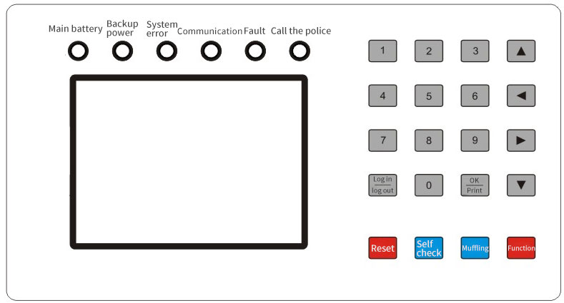
2) Button functions and instructions
① Reset:
After device reset is completed, all states of the system are reinitialized. (This function can be operated under the login state)
②Self-inspection:
Complete the self-test of the device. The self-test content includes: fault sound, alarm sound, indicator light, printer, etc.
③ Muffling:
When the device detects a fault message or an alarm message, it will be accompanied by a corresponding fault or alarm sound. This key can temporarily eliminate the sound, but if there is a new fault or alarm message after the sound is muted, the sound will restart.
④Function:
Switch the display window, view and set the parameters of each window
⑤ Login, logout:
When you are not logged in, press the login and logout keys, and the cursor will flicker in the unlogged area at the bottom of the window. At this time, enter the 8888 password-login is successful, and press the login and logout keys again to log out.
⑥ OK, print key:
It is used to confirm or save when logging into the system and setting parameters. In addition, it is also used as manual printing when there is a fault page.
⑦Other keys:
Numeric keys or up, down, left, right (cursor) positioning keys.
Installation Notes
1)Engineering Wiring Requirements
① A monitoring device can be connected with at most (such as 32* loop number) detectors, and the loop number is ≤16; the specific models are: 32*/64*/128*/256*
② The communication line between the monitoring equipment and the detector should be a twisted pair, and the wire diameter should not be less than 1.5mm2. The longest laying distance of the communication line should be less than 1200m. If the use distance of the communication line exceeds 1200m, a repeater should be added. When the system is applied in a place with strong interference, the communication line should use a shielded twisted pair;
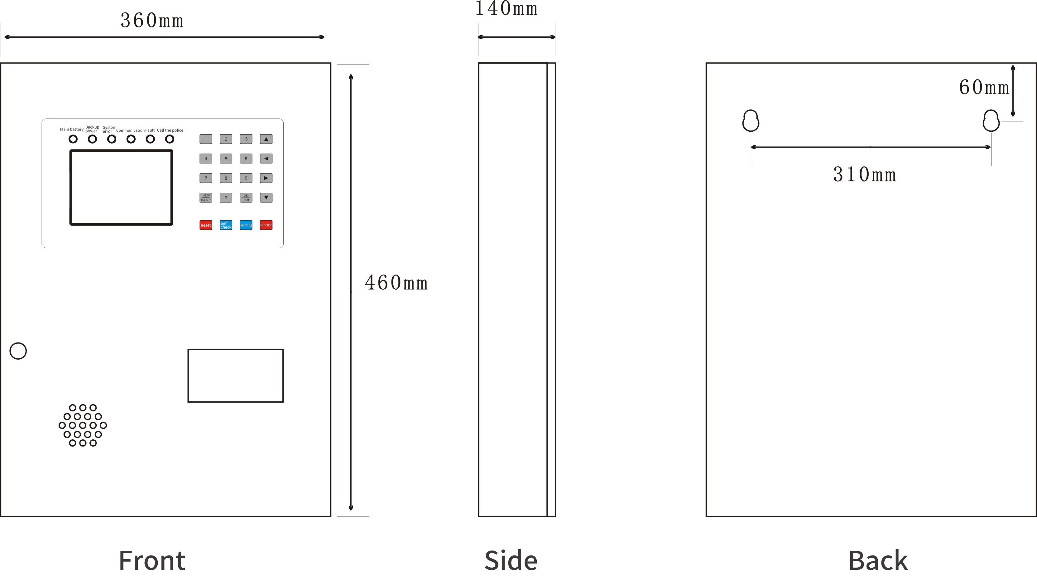
2)Dimensional drawing:
3)Wiring Instructions:
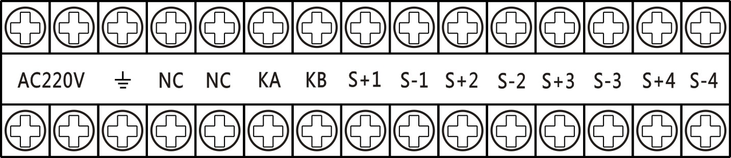
N, L: AC 220V power input
 :Chassis ground, connected to the earth
NC: is a blank terminal
KA, KB: Control output (normally open contact, capacity AC250V/5A)
S+1, S-1: 1-loop two-bus communication interface (communication with the detector)
S+2, S-2: 2-loop two-bus communication interface (communication with the detector)
S+3, S-3: 3-loop two-bus communication interface (communication with the detector)
S+4, S-4: 4-loop two-bus communication interface (communication with the detector)
Note: Because the configuration of the device is different, the wiring terminals may be different, the actual object shall prevail
|
product name |
product model |
basic function |
remarks |
||
|
Electrical fire monitoring host |
NLK888 |
|
Management and monitoring Each detector |
200 Units |
Touch screen wall mounted 470mm * l50mm * 370mm wall mounting type 400mm *130mm *550mm |
|
32 Units |
|||||
|
64 Units |
|||||
|
128 Units |
|||||
|
256 Units |
|||||