GY600 motor protector

Product overview
Motor protection device is researched and developed to protect and control motor with high performance digital microprocessor technology, based on the research of similar products abroad and summary of MCC electrical system home.The motor protection device possess international advanced protection function, support professional way of motor control and provide accurate monitoring function, can run for a variety of motor control, monitoring, protection, interlock, measure, remote communication, remote communication, remote control, fault information management.
The motor protection device is a kind of multi-functional protector, greatly improve the design and the production efficiency and reduces the user site debugging and maintenance cost,, so as to improve the scene of the scientific and effective protection of the production process, the measurement and control unit, which is protected by intellectual property and software copyright.
Motor protection device adopt modular design structure, with those advantages of small in size, compact structure, guide rail or the self-contained bolt installation, suitable for various kinds of stationary and drawer cabinet where can be installed directly to use.Apply to three-phase asynchronous motor and motor protection control, motor production device is the best ideal products for many fields such as chemical, petroleum, electric power, mining, coal, metallurgy, municipal, paper making, the nuclear industry involving three-phase motor protection.
Technical parameters
| Working power supply | AC85-265V 50Hz | ||||
| Main circuit power supply voltage | ≤AC1160V | ||||
| Control relay output | Passive contact 5A | ||||
| Installation | Standard 35 mm guide installation, screws fixation | ||||
| Applied range | Three-phase industrial equipment | ||||
| Over voltage protection | voltage values setting | 110-465 available | |||
| Low voltage protection | voltage values setting(V) | 0-380 available | |||
| Overload (flow) protection | Current Setting A | A can be set in the specified current | |||
| Actuation time S | 1-255 available | ||||
| Underload (flow) protection | Current Setting A | A can be set in the specified current | |||
| Actuation time S | 0-255可设 | ||||
| Open-phase protection | Percentage setting | 1-100 available | |||
| ground protection | Current setting of electric leakage(mA) | 500-5000mA available | |||
| Programmable Control of the action | |||||
| Motor Shaft Lock Protection | Magnification setting | 1-9 times available | |||
| Start timeout protection | Start delay time setting | 1-255 available | |||
| Fault resetting | hand reset | 0 | |||
| automatic reset | 0-255 available | ||||
| 20 mA Corresponding current | Set 20 mA with a corresponding to the current value of the output | ||||
| Mailing address | network communication identification | 1-255 available | |||
| Starting mode | Ways | Direct starting, star triangle starting, positive and negative starting, direct start, positive and negative bypass circuit starting, reduction voltage starting | |||
| Relay packing time | Packing time | 1-255s available | |||
| Programmable relay | Start time and leakage time, fault tripping, on time and alarm time | ||||
| Programming relay output time | Output time S | 1-255s available | |||
| Overload control protection | When the motor overload carrying, control protection device track and calculate overload current according to the heat capacity (Q) of the motor thermal. In thermal overload protection fully considered in the calculation of the motor stator and rotor temperature rise, meanwhile considering the unbalanced three-phase affect motor heatin. When the current increases to control protection value, giving alarm prompt action to trip value time. | ||||
| Underload (flow) protection | when protected current through less than the setting value, action set alarm, and give the alarm or stop work. | ||||
| Motor Shaft Lock Protection | To prevent the occurrence of severe motor running blockage or motor overload operation while the multiple of current reach setting current, give signal alarm or stop | ||||
| Unbalance protection of three-phase current | Through three phase current or three-phase voltage according to the ratio of the minimum line current and maximum line current alarms when the set values for the reach or exceed hint to trip condition | ||||
| Open-phase protection | When any phase in three phase current in the current ratio is greater than the imbalance Angle value is defined as the phase failure fault | ||||
| Over voltage protection | Monitor three-phase voltage values, any phase voltage higher than the set value alarm prompt in action time | ||||
| Low voltage protection | Monitor three-phase voltage values, any phase voltage lower than the set value alarm prompt in action time | ||||
| ground protection | Through external zero sequence current transformer measurement, according to the current of motor phase the conductor (PE) or (PEN) whether to start the leakage fault protection function, when greater than the setting values of the leakage protection device, protective device sends an alarm to trip time | ||||
| Anti-interference protection | monitor continuously the voltage of the equipment, when the system voltage instantaneous fall then recover, motor can restart | ||||
| Start timeout protection | Continuously monitor the starting current delay time, when the current is greater than the delay time to complete the boot device, three phase current was 1.2 times greater than the set current start timeout tripping protection action | ||||
| Reverse protection | When detect three-phase voltage phase sequence is not correct, stop and can not start the motor | ||||
| External fault protection | When check the external switch input signal and the default state of switch input is inconsistent, the device can not start | ||||
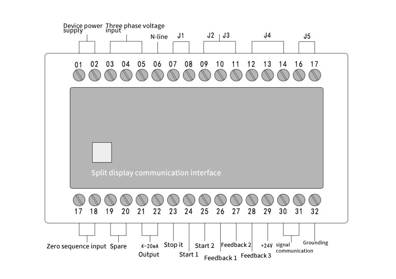
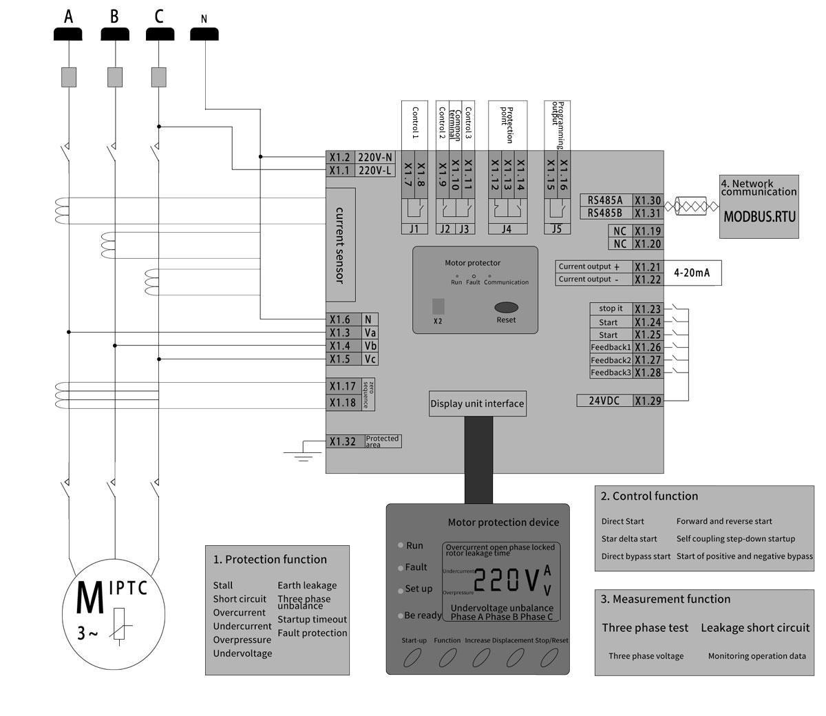
Terminal definition(Less than1.5mm)
| Terminal number | Instructions |
| X1.1…2 | Working power AC/DC220V input |
| X1.3…5 | Three-phase voltage input |
| X1.6 | N neutral input |
| X1.7…8 | control relay J1 |
| X1.9…10 | control relay J2 |
| X1.10…11 | control relay J3 |
| X1.12…13 | Output relay protection J4 closed |
| X1.13…14 | Output relay protection J4 opened |
| X1.15…16 | Programmable output relay J5 |
| X1.17…18 | zero sequence current input |
| X1.19…20 | reserved output |
| X1.21…22 | (X1.21 For + X1.22 For -) 4-20mA output |
| X1.23 | SDS stop input |
| X1.24 | DCS start 1 input |
| X1.25 | DCS start 2 input |
| X1.26,27,28 | Equipment feedback input |
| X1.29 | DC24V output, state quantity driven |
| X1.30…31 | (X1.30 For A X1.31 For B)RS485 communication interface |
| X1.32 | Apparatus ground |
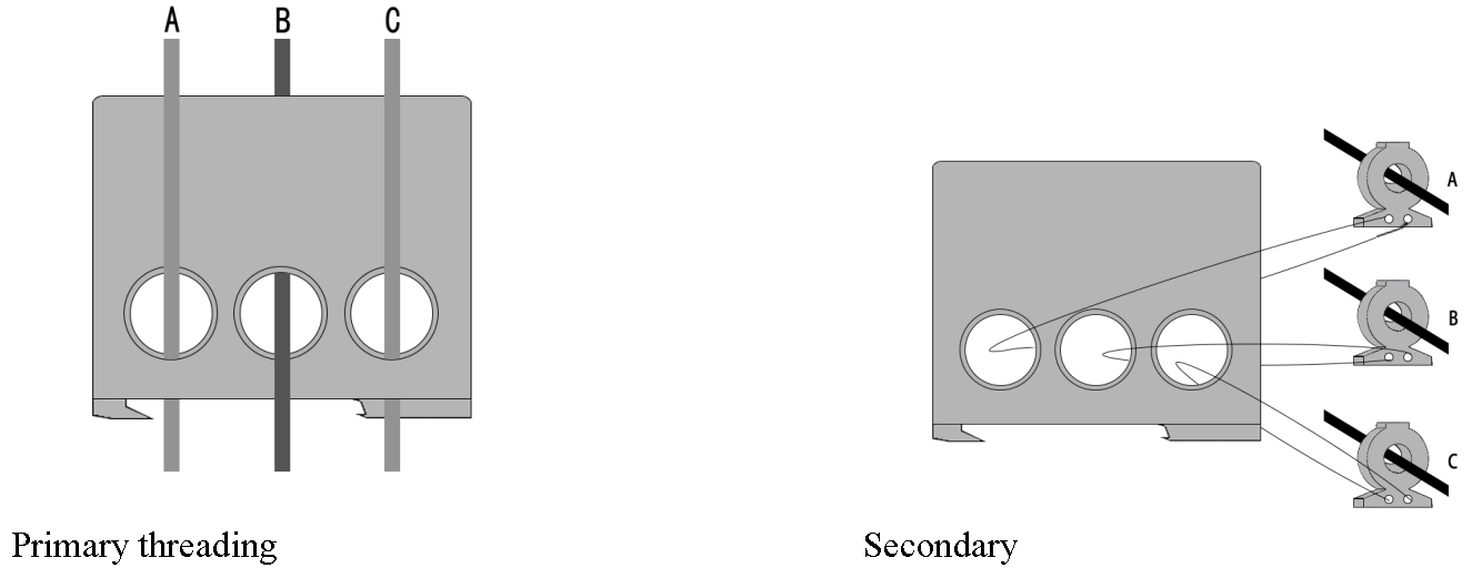
Note: the motor is less than 0.5KW, the main circuit go through the protection device to be around the line, to ensure no-load current greater than 1A.
Note: The motor power cord directly go through the standard current transformer hole, the standard current transformer secondary output line go through from the protection device current transformer wire hole directly .
Typical connection mode
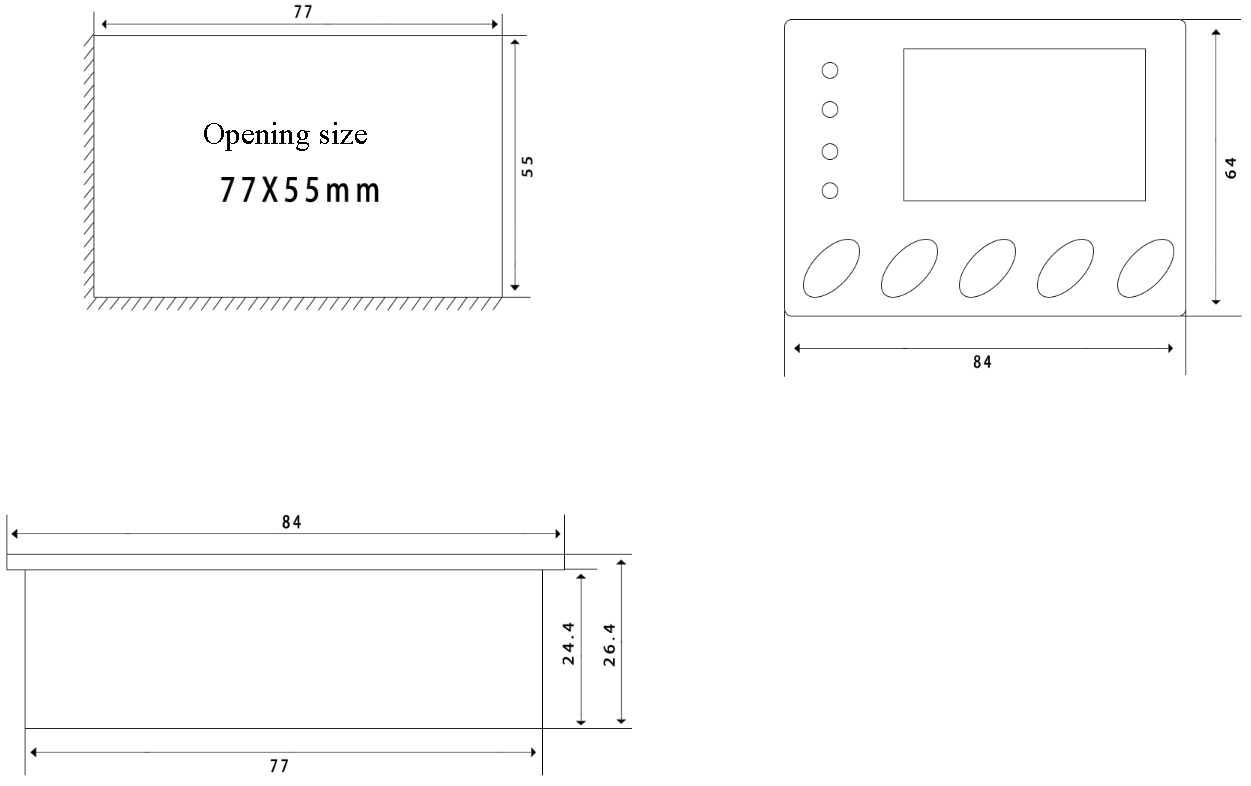
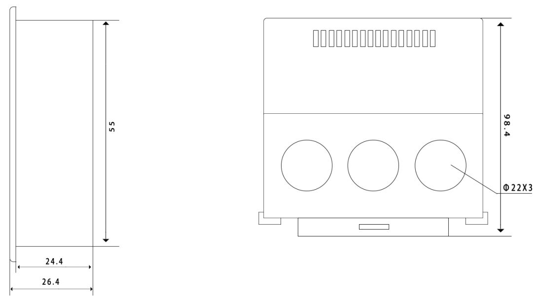
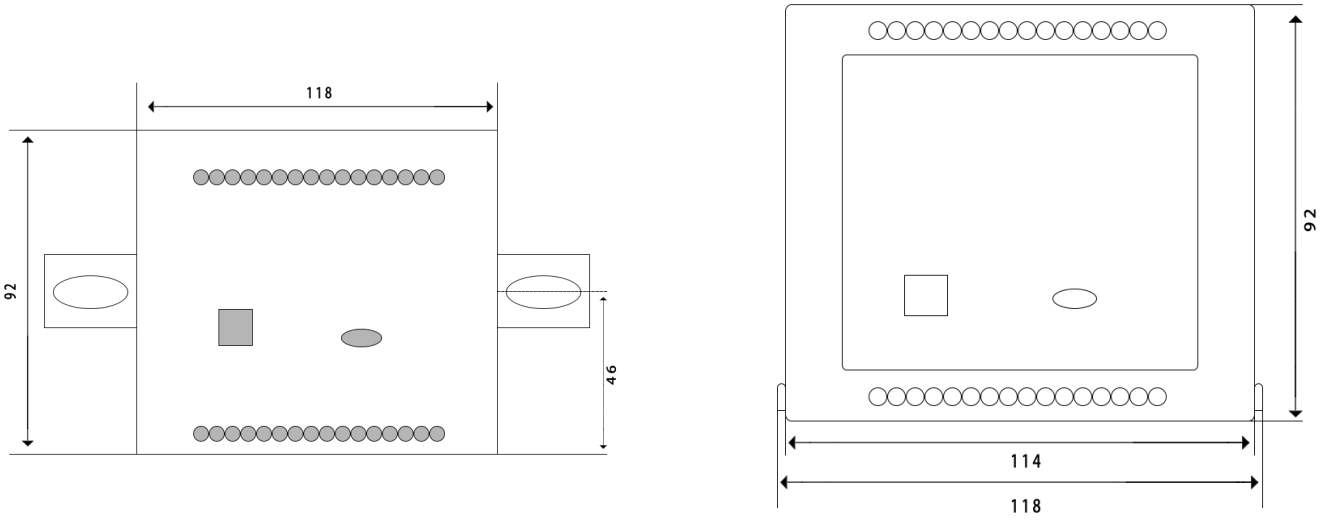
Contour installation
|
product name |
product model |
basic function |
remarks |
|
|
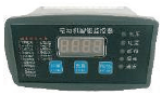
Motor protector |
NLK100H |
|
Economical electric motor protector Split type and one-piece type |
Guide rail installation or open hole installation 91mm * 44mm |
|
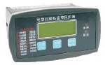
NLK310H |
|
Conventional intelligent electric motor protector Split type and one-piece type |
||
|
NLK500 enough functional motor protector with start button |
|
Blocking rotation, phase breaking, overcurrent, three-phase current imbalance, overvoltage, undervoltage, short circuit, leakage and other fault protection, three-phase current measurement, display the working voltage |
Open hole is 92mm * 66mm |
|
|
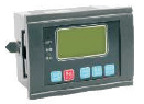
NLK600H high-end motor protector |
|
Overcurrent, blocking, phase breaking, three-phase current Unbalanced overvoltage, undervoltage, short circuit, leakage (optional) and other fault protection, phase current, phase voltage, line voltage frequency, active power, reactive power, power factor measurement multi-channel switch quantity signal |
Open hole is 77mm * 55mm |
|
|
NLK800H high-end motor protector |
|
Open hole is 90mm * 90mm |
||