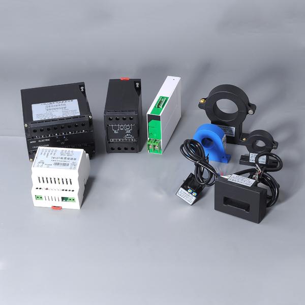
Power Transmitter


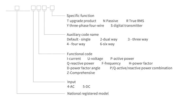
Naming meaning
General technical indicators
|
Citation Standards and Rules |
GB/T13850-1998 |
|
|
Input overrange |
Continuous: 1.2 times; Instantaneous: current 10 times (5 seconds), voltage 2 times (10 seconds) |
|
|
Enter frequency |
50/60Hz±10% |
|
|
Insulation strength |
AC 2kV |
|
|
Isolation withstand voltage |
Between standard input and output: AC 1KV; power supply and input, power supply and output: AC 2KV |
|
|
Insulation resistance |
≥1000 |
|
|
Output ripple |
Basic error value not greater than 2 times |
|
|
Working conditions |
Ambient temperature: -10~+55℃, relative humidity ≤93%, |
|
|
Storage conditions |
Temperature -40~+70℃, relative humidity 20~+99℃, no condensation |
|
|
MTBF |
≥50000h |
|
| Note: The nominal value of input signal 0~100% generally corresponds to the output of 4~20mA (special circumstances will be specified separately). | ||
List of specifications and models
|
Product name |
Input mode |
Output Settings |
illustrate |
Auxiliary power |
|||
|
4-AC |
5-AC |
Analog quantity |
Digital quantity |
Energy pulse |
|||
|
One way |
● |
● |
1 way |
AC、DC |
|||
|
● |
● |
1 way |
|||||
|
● |
2 way |
2 in 2 out or 1 in 2 out, isolated from each other |
|||||
|
● |
2 way |
||||||
|
● |
1 way |
True RMS measurement |
|||||
|
● |
1 way |
||||||
|
● |
● |
√ |
Digital transmission |
||||
|
● |
● |
√ |
|||||
|
● |
1 way |
External low-voltage DC power supply is required |
DC 12V |
||||
|
● |
1 way |
||||||
|
Three-way current transducer |
● |
3 way |
AC、DC |
||||
|
Three way voltage transmitter |
● |
3 way |
|||||
|
Power Transmitter |
● |
1 way |
Three-phase three-wire |
||||
|
● |
1 way |
||||||
|
● |
1 way |
Three-phase four-wire |
|||||
|
● |
1 way |
||||||
|
● |
4 way |
√ |
|||||
|
frequency transmitter |
● |
1 way |
|||||
|
● |
√ |
||||||
|
Power Factor Transmitter |
● |
1 way |
|||||
|
● |
√ |
||||||
|
Power factor |
● |
1 way |
|||||
|
● |
√ |
||||||
|
Comprehensive power transmitter |
● |
4 way |
√ |
2 way |
Combined transmission |
||
| Note: ● indicates that there is this input method: √ indicates that there is RS-485 interface digital output function. | |||||||
Recommended Products
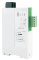
Single-phase current, single-phase voltage transmitter
It can measure current and voltage signals, and output them as DC current or voltage analog signals after signal processing and isolation. The power supply of this transmitter is powered by a switching power supply, which can work well in an environment with large fluctuations in the power grid.
Product model
◇AC current transmitter
◇DC current transmitter
◇AC voltage transmitter
◇DC voltage transmitter
Technical indicators
| Specification Model Indicator |
BS41 |
BS51 |
BS4U |
BS5U |
||
|
Accuracy class |
0.2 level 0.5 level |
|||||
| Input |
Nominal |
1A、5A etc |
20mA etc |
100v、220V、380V etc |
75mV etc |
|
|
frequency |
50/60Hz±10% |
|||||
| Output |
Aanalog quantity |
Nominal |
0~20mA、4~20mA、0~5V etc |
|||
|
Load Resistance |
Current output: RL<1kΩ; voltage output: RL≥5kΩ |
|||||
|
Digital quantity |
RS-485 interface MODBUS-RTU protocol; baud rate: default 4800 (optional 2400, 9600) bps |
|||||
| Power supply |
Auxiliary power |
Ac、DC 80~270v |
||||
|
Power dissipation |
≤3.5VA |
|||||
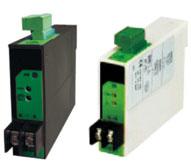
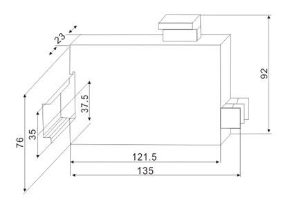
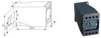
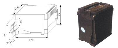
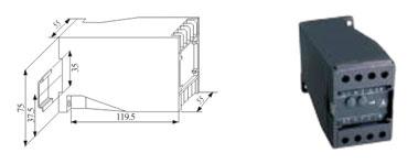
External dimensions
Installation method
It can be fixedly installed on a 35mm standard rail.
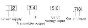
Wiring method
Export-type single-phase current, single-phase voltage transmitter
The AC current and voltage transmitter is an instrument that can linearly scale the measured AC current and voltage and isolate and convert the output DC current or voltage. Equipped with corresponding indicating instruments or devices, the measurement and control of current and voltage can be realized in the power system circuit. The true RMS transmitter does not affect the accuracy with the waveform distortion, and is especially suitable for areas with severe waveform distortion.
Installation method
It can be fixedly installed on a 35mm standard guide rail, and can also be used for screw fixing.
Product model
◇AC current transmitter
◇DC current transmitter
◇AC voltage transmitter
◇DC voltage transmitter
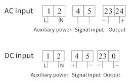
Wiring method
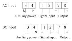
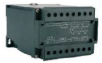
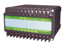
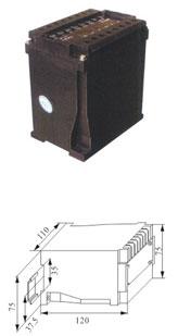
Three-way current, voltage combination transmitter
The three-phase AC current and voltage transmitter is an instrument that can convert the measured three-phase AC current or voltage into a DC current or voltage that is isolated and converted in a linear ratio. Equipped with corresponding indicating instruments or equipment, the measurement and control of current or voltage can be realized in the AC circuit of the power system.
Product model
◇Three-way AC current transmitter
◇Three-way AC voltage transmitter
Technical indicators
| Specification Model Indicator |
BS413 |
BS4U3 |
|
|
Accuracy class |
Level 0.5, Level 0.2 (True RMS input) | ||
| Input |
Nominal input |
AC1A, 5A, etc. |
AC100V, 220V, 380V, etc. |
| Output |
Analog output |
Simultaneously la, lb, lc three quantities |
Simultaneously Uab, Ubc, Uca or Uan, Ubn, Ucn three quantities |
|
Rated value |
4~20mA, 4~12~20mA, 0~5V, etc. | ||
|
Load Resistance |
Voltage output RL>100KΩ, current output RL<510KΩ | ||
| Power supply |
Auxiliary power |
AC/DC 80V~270V | |
|
Power dissipation |
<5VA | ||
|
Communication output |
Optional RS485 interface, MODBUS-RTU protocol, baud rate: default 4800 (optional 2400, 9600) bps | ||
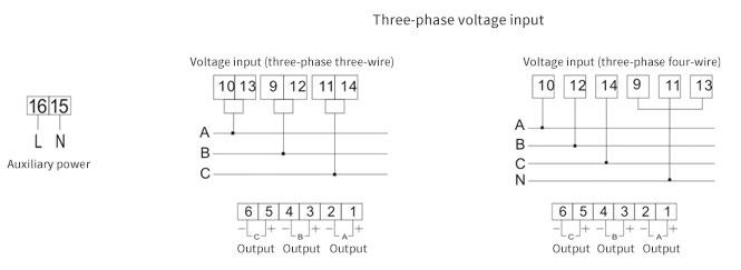
Note: Considering the user's receiving equipment, there are two situations for the voltage signal transmission output:
When the input voltage is three-phase three-wire, 0~120% of the nominal value corresponds to the transmission output 4~20mA
When the input voltage is three-phase four-wire, 0~100% of the nominal value corresponds to the transmission output 4~20mA
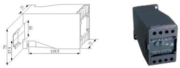
External dimensions
Installation method
Installed on a 35mm standard guide rail or fixed on the cabinet with screws.
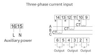
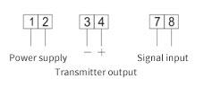
Wiring method
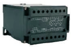
Frequency Transmitters
A frequency transmitter is an instrument that converts the measured frequency signal into a DC current or voltage that is linearly proportional to the isolated conversion output. Equipped with corresponding indicating instruments or equipment, it can realize the measurement and control of the grid frequency signal in the AC circuit of the power system.
Product specification
frequency transmitter
Installation method
Installed on a 35mm standard guide rail or fixed on the cabinet with screws.
Wiring method
External dimensions
Power Factor Transmitter
A power factor transmitter is an instrument that converts the measured power factor signal into a DC current or voltage that is isolated and converted in a linear ratio. Equipped with corresponding indicating instruments or equipment, it can realize the measurement and control of the grid power factor in the AC circuit of the power system.
Product specification
Power Factor Transmitter
Installation method
Installed on a 35mm standard guide rail or fixed on the cabinet with screws.
Wiring method
External dimensions
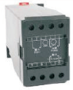
Active/reactive power combination transmitter
The active/reactive power combination transmitter only needs a set of input connection wires, and only occupies one transmitter space to measure active power and reactive power at the same time, active power and two isolated DC outputs corresponding to reactive power , so it is the most economical supporting instrument for active power and reactive power measurement.
Product Specifications
Three-phase three-wire active power transmitter
Three-phase four-wire active power transmitter
Three-phase three-wire reactive power transmitter
Three-phase four-wire reactive power transmitter
Wiring method

External dimensions
|
product name |
product model |
basic function |
remarks |
|
|
AC current transmitter |
NLK600-BS4I |
|
Single-phase current, single-phase voltage transmitter Can measure the current and voltage signals, After signal processing and isolation in DC flow Or voltage analog signal output.This transmitter Power supply to switch power supply, can work well in the grid fluctuating environment.
|
Length * width * height of 92mm * 23mm * 135mm respectively |
|
DC electric current transmitter |
NLK600-BS5I |
|||
|
AC voltage transmitter |
NLK600-BS4U |
|||
|
DC electric voltage transmitter |
NLK600-BS5U |
|||
|
AC current transmitter |
NLK700-BS4I |
|
Can measure the current and voltage signals, After signal processing and isolation in DC flow Or voltage analog signal output. Export type single phase current, single phase voltage transmitter |
Length: * width: * height: 75mm: * 55mm: * 120mm |
|
DC electric current transmitter |
NLK700-BS5I |
|||
|
AC voltage transmitter |
NLK700-BS4U |
|||
|
DC electric voltage transmitter |
NLK700-BS5U |
|||
|
Three-way AC current transmitter |
NLK600-BS4I3 |
|
Three-way current and voltage combination transmitter Three-phase AC current and voltage transmitter is an instrument that can convert the measured three-phase AC current or voltage into the mainstream conversion output in a linear proportion.With the corresponding indicator instrument or equipment, the current measurement and control or voltage can be realized in the power system AC circuit. |
Length, * width, * height, 110mm * 75mm * 120mm |
|
Three-way AC voltage transmitter |
NLK600-BS4U3 |
|||
|
Frequency transmitter |
NLK600-BS4F |
|
A frequency transmitter is an instrument that converts the measured frequency signal into a DC current or voltage for isolating the converted output in a linear scale. |
Length: * width: * height: 75mm: * 55mm: * 120mm |
|
Power factor transmitter |
NLK600-BS4H |
A power factor transmitter is an instrument that converts the measured power factor signal into a converted output DC current or voltage in a linear scale |
||
|
Active power transmitter |
NLK600-BS4P |
|
The power transmitter will input three-phase three lines or three-phase four lines of voltage and current signals into the success rate of linear transmission output DC current or voltage instrument |
Length, * width, * height, 110mm * 75mm * 120mm |
|
Reactive power transmitter |
NLK600-BS4Q |
|||