


Switch Cabinet Intelligent Control Device


Technical indicators
1. Working voltage: Device power supply: AC/DC220V±10% 50HZ.
Load power supply: AC220V±10%50HZ.
2. Voltage loop power consumption: ÿ15VA.
3. Dielectric strength: ÿAC2000V between the shell and the terminal.
4. Insulation performance: more than 100Mÿ between the shell and the terminal.
5. Communication: RS485 interface, factory default address, baud rate 9600.
6. Temperature and humidity control range: temperature 0ÿ-99ÿ humidity 0%RH-95%RH.
7. Measurement accuracy: Temperature ±2ÿ Humidity ±5%RH.
8. Working environment: normal working temperature -20 ÿ-70 ÿ.
Annual average humidity ÿ 95%.
Anti-electromagnetic interference performance: in line with the standard provisions of IEC60255-22.
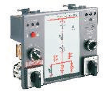
Panel and function description
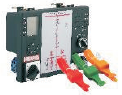
1. Panel description of digital intelligent control device:
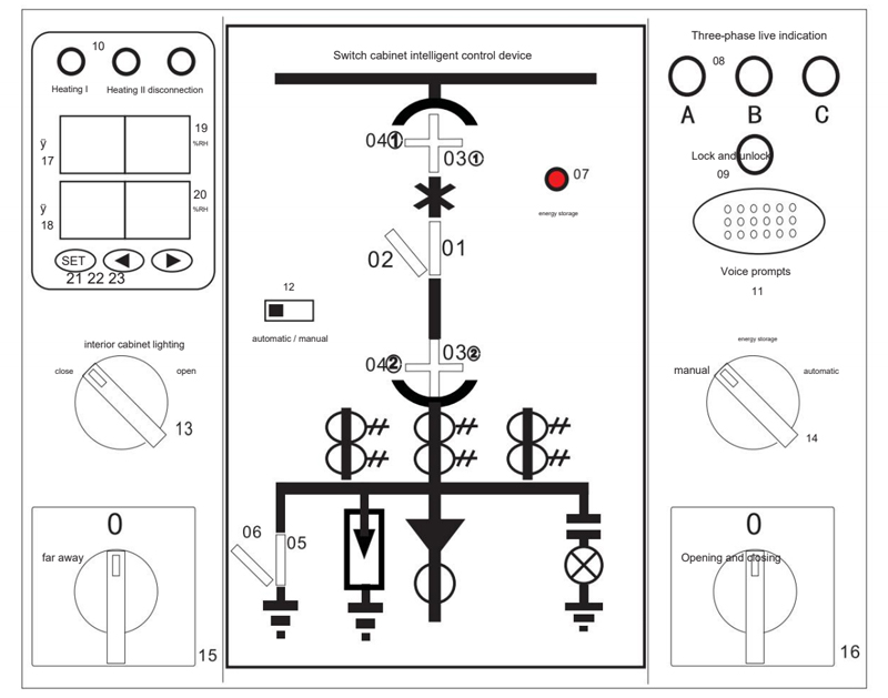
(Note: The numbers in the figure are to illustrate the indication function of the layout, and there is no number on the actual instrument)
01. Circuit breaker closing indication
02. Circuit breaker opening indication
03.①, 03② Working position indication
04.①, 04② Test position indication
05. Grounding switch closing indication
06. Grounding switch sub-indication
07. Energy storage indication
08. Live indication (ABC) three-phase
09. Lockout indication
10. Heating and dehumidification indication
11. Voice prompt
12. Manual automatic heating switch
13. Cabinet lighting knob switch
14. Energy storage knob switch
15. Remote/local transfer switch
16. Opening/closing transfer switch
17. The first temperature display
18. The second temperature display
19. The first humidity display
20. The second humidity display
21.SET: Menu key and OK key
22. ◀ Value increase key
23.▶Numerical decrease key
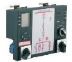
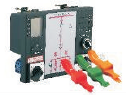
2. Panel description of ordinary intelligent control device:
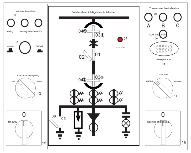
(Note: The numbers in the figure are to explain the indication function of the layout, and there is no number on the actual instrument)
01. Circuit breaker closing indication
02. Circuit breaker opening indication
03.①, 03② Working position indication
04.①, 04② Test position indication
05. Grounding switch closing indication
06. Grounding switch sub-indication
07. Energy storage indication
08. Live indication (ABC) three-phase
09. Lockout indication
10. Heating and dehumidification indication
11. Voice capture
12. Manual automatic heating switch
13. Cabinet lighting knob switch
14. Energy storage knob switch
15. Remote/local transfer switch
16. Opening/closing transfer switch
Function description
(1) Circuit breaker status display:
When closing, the closing contact is closed, and the red analog bar 01 lights up.
When opening, the opening contact is closed, and the green analog bar 02 lights up.
(2) Display of handcart position:
When the working position contact is closed, the red vertical analog bar 03 lights up.
When the test position contact is closed, the green horizontal analog bar 04 lights up.
(3) Grounding knife position indication:
The contact is closed, and the red analog bar 05 is on, indicating that the grounding is closed.
The contact is disconnected, and the green analog bar 06 is on, indicating that the grounding is disconnected.
(4) Energy storage status indication:
The contact is closed, and the red light 07 is on, indicating that the energy has been stored.
Note: In the power-off state, all the luminous indications are off, and the above contact signals are all from the auxiliary contacts of the circuit breaker.
(5) High voltage live indication LED starting voltage (KV): bus voltage × 0.150.65.
Latching start control voltage (KV): busbar voltage × 0.65.
(6) Temperature and humidity control function:
Number of sensor channels: two channels of condensation + two channels of temperature or one channel of condensation + one channel of temperature.
Logical relationship: start heating when temperature <5℃ or humidity>90%RH (two-way heating);
Stop heating when temperature>15℃ or humidity<80%RH;
When the temperature is >45℃, the output of the overheat exhaust air relay;
When the temperature is less than 35°C, the overheated exhaust air stops outputting.
Disconnection alarm: The temperature and humidity sensor or heater is disconnected, and the corresponding alarm indicator light is on.
Manual heating switch: The switch can be in two states, automatic or manual, usually in the automatic state. At this time, the temperature and humidity control logic is the same as above. When the switch is pressed, it is in the manual forced heating state.
(When the ambient temperature is lower than 15°C, after the general heating is canceled, the heater will stop heating to 15°C)
(7) Intelligent anti-mistake voice prompt:
When the handcart is between the test position and the working position, when the circuit breaker is in the closed state, there will be a voice prompt of "Please open the circuit breaker" until the circuit breaker is opened;
When the handcart is not in the test position or working position, if the grounding switch is forced to close by mistake, there will be a voice prompt of "Please disconnect the grounding switch" until the grounding switch is opened;
When the circuit breaker is closed and the handcart is not in the test position or working position, if the grounding knife switch is forced to close by mistake, there will be a voice prompt of "Please disconnect the circuit breaker, please disconnect the grounding switch";
When the device is powered on, there will be a voice prompt "This circuit is live, do not approach it";
When the device is powered on and the three-phase high voltage is charged, there will be a voice prompt of "This circuit is live, do not approach it".
(8) Communication function:
The device can be equipped with an RS485 communication interface, which can transmit real-time temperature and humidity values in real
time, switch state position, heating, disconnection, exhaust, lock and other states, three-phase high-voltage live state and a series of parameters (Refer to the communication protocol for details).
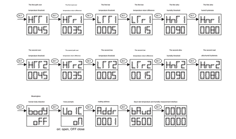
(9)Description of the digital control device setting menu:
Fourth, wiring instructions
Terminal wiring diagram of digital and common control devices
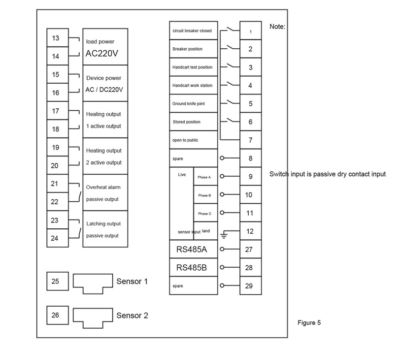
Wiring description:
(1) The power supply terminals of the device are 15 and 16, the voltage is AC/DC220V or 110V±10%, and the load power supply terminals are 13 and 14.The voltage must be AC220V±10%. The standard configuration of the device is that the heater output is active, and the load power supply must be wired; if the device is a passive heater output, the load power supply does not need wiring, please specify when ordering.
(2) Some terminals of the primary circuit analog display are: 1-7, and all switching values are passive contacts. The above is the standard configuration of the device. The specific terminal definitions will be changed according to the different ordering requirements of users, and the terminal definitions on the back of the device shall prevail.
(3) The wiring method of the accessory temperature and humidity sensor line is: connect the USB plug-in connector to the temperature and humidity sensor terminals (25, 26) of the device. Connect the other end to the matching temperature and humidity sensor.
(4) Others can be connected to the working power supply only after the wiring is connected according to the terminal wiring diagram of the device and checked correctly.
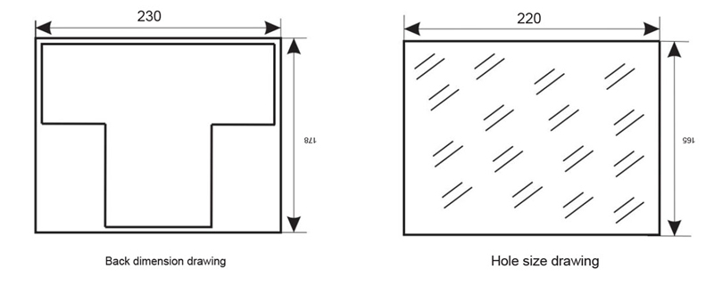
Installation method
1. Installation methods of digital and ordinary intelligent control devices:
This product is panel-mounted, and its standard accessories include: temperature and humidity sensor, temperature and humidity sensor cable, mounting bracket, green terminal, etc. When installing, you only need to make holes on the panel of the switch cabinet. The size of the opening of the switch cabinet is 220mm × 165mm. To insert the device into the opening, you only need to use three mounting brackets to fit into the fixing holes of the device and then tighten, and tighten the screws.
| product name | product model |
basic function |
remarks |
|
|
Indicator lamp type Intelligent control device |
NLK5000A |
|
First circuit simulation diagram, circuit breaker position, working state of manual experiment, grounding switch position spring energy storage state, high voltage live indication, high voltage live lock and two temperature and humidity control, cabinet lighting, energy storage, switch, remote local switch, with nuclear phase (power inspection) and + 50, with self-inspection and + 50 |
Open hole is 220mm * 165mm |
|
The number of explicit Intelligent control device |
NLK5000S |
|
First circuit simulation diagram, circuit breaker position, working state of manual experiment, grounding switch position spring energy storage state, high voltage live indication, high voltage live lock and two temperature and humidity control, cabinet lighting, energy storage, switch, remote local switch, with nuclear phase (power inspection) and + 50, with self-inspection and + 50 |
Open hole is 220mm * 165mm |
|
LCD type Intelligent control device |
NLK5000Y |
|
First circuit simulation diagram, circuit breaker position, working state of manual experiment, grounding switch position spring energy storage state, high voltage live indication, high voltage live lock and two temperature and humidity control liquid crystal display, cabinet lighting, energy storage, switch, remote local switch, if you need to increase more power measurement, an additional 200 yuan should be added.With nuclear phase (power test) another + 50, with self-inspection another + 50 |
Open hole is 220mm * 165mm |
|
Wireless point-temperature control device Battery power supply type |
NLK5000D |
|
A loop simulation diagram, circuit breaker position, hand car experiment working state, ground switch position spring energy storage state, high voltage charged indication, high voltage live lock, two road temperature and humidity control LCD, cabinet lighting, energy storage, switch, remote local switch, wireless temperature measurement, battery power supply type, if need to increase more power, need to add 200 yuan.Note: According to 6 points of quotation, each additional point plus + 80 yuan. |
Open hole is 220mm * 165mm |
|
Wireless point-temperature control device (Self-collected power) |
NLK6000D |
|
First circuit simulation diagram, circuit breaker position, switch state, grounding switch position spring energy storage state, high voltage live indication, high voltage live lock, two humidity control LCD display, cabinet lighting, energy storage, switch, remote local switch, wireless temperature measurement, self-power, if you need to increase more power measurement, need to add 200 yuan.Note: According to 6 points of quotation, each additional point plus + 100 yuan. |
Open hole is 220mm * 165mm |

Related products
-
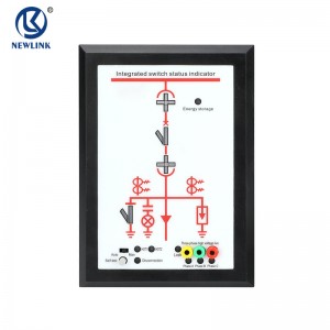
Switch State Indicator
Panel and function description Description of the switch status indicator panel: (Towards: the numbering in the figure is to illustrate the indication function of the layout, and there is no numbering on the actual instrument) 01. Circuit breaker closing indication 02. Circuit breaker opening indication 03.①, 03②Working position indication 04.①, 04②Test position indication 05. Grounding switch closed indication 06. Earthing switch sub-indication 07. Energy storage i...
-
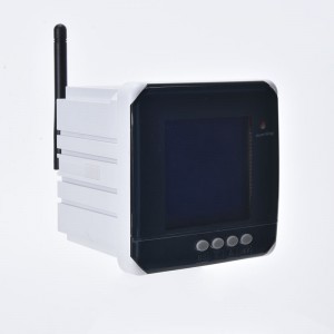
Wireless Temperature Measurement Device
Product description This product is a new concept wireless temperature measuring device for switch cabinets. It has powerful functions and is suitable for various switch cabinets such as central cabinets, handcart cabinets, fixed cabinets, and ring network cabinets in 3-35KV indoors. This product adopts the intelligent control of single-chip microcomputer, which can collect the temperature and humidity in the cabinet in real time, and automatically adjust the tempera...

