


Fire power host

Overview
The fire equipment power supply status monitoring host is researched and developed according to the national standard “Fire Equipment Power Supply Monitoring System” and is specially used for real-time monitoring of the fire equipment power supply status. The fire equipment power supply status monitor, voltage signal sensor and current signal sensor form a fire equipment power supply monitoring system, which can monitor the working status of the fire equipment power supply in real time. When the power supply is interrupted, overvoltage, undervoltage, phase loss, and overvoltage When a fire occurs, it can effectively avoid the critical situation that the fire fighting equipment cannot work normally due to a power failure, and ensure the reliability of the fire linkage system to the greatest extent.
The fire equipment power supply status monitoring host is the core of the fire equipment power supply status monitoring system, which can display various working states of the monitored circuit in real time. When the system is abnormal (interruption, overvoltage, undervoltage, phase loss, and overcurrent (overload) and other failure information will send out alarm signals), the monitoring equipment will send out sound and light alarm signals to remind the staff to pay attention; and Display and record specific content.
The fire equipment power status monitoring system implements the national standard GB 28184-2011 “Fire Equipment Power Status Monitoring System”.
Basic function
The power supply status monitoring host of fire fighting equipment uses ARM microcontroller (single chip microcomputer + embedded software) as the main controller, and connects each sensor through the PB fire fighting second bus to monitor the running status of all controlled loops in the system in real time.
1. Alarm function
When the controlled circuit is abnormal, such as: power supply interruption, overload, etc., the fire equipment power supply status monitoring host can immediately indicate the alarm type of the faulty circuit, and alarm with sound and light.
2. System status indication and alarm function
When there is a communication failure or power failure (main power failure, backup battery failure, etc.) in the monitoring system, the fire equipment power supply status monitoring host can indicate the type of failure and give an audible and visual alarm.
3. Report printing function
When the controlled circuit is abnormal (generated, alarmed) or the system fails (communication line disconnection, main power failure, backup battery failure, etc.), the fire equipment power supply status monitoring host can indicate the type of failure, and alarm with sound and light At the same time, the fault information report can be automatically printed through the printer, and the fault history information can also be printed manually.
4. Telemetry function
The fire equipment power supply status monitoring host can detect the working status of each controlled circuit in real time, and display the current, voltage, and other parameters of each controlled circuit.
5. History (fault)
The power supply status monitoring host of fire-fighting equipment can store alarm information, fault and other information.
Setting and working status description
When the power supply status monitoring host of fire-fighting equipment is in normal operation, manual intervention is generally not required until the system alarms or fails. However, you should read this manual in detail when you run it for the first time, so as to set its parameters and ensure that it works in a normal monitoring state.
When the power supply status monitoring host of fire-fighting equipment is working normally, the corresponding fault or alarm lights should be off, and no fault or alarm sound will be issued, and the LCD screen will display the corresponding measured parameters. If there is a fault or alarm message, the corresponding fault or alarm light will light up, accompanied by a fault or alarm sound.
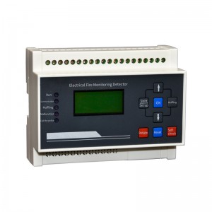
1.Device Panel Description
Outline drawing of fire equipment power status monitoring host:
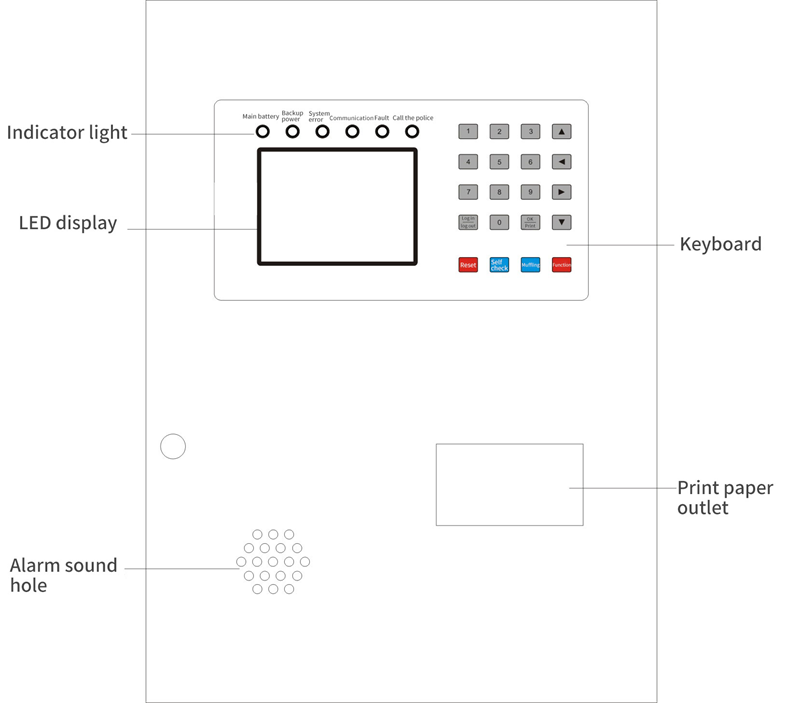
Host panel function description :
1) Display screen:
Display system status parameter information, man-machine dialogue function parts.
2) Indicator lights:
① Main power indicator: When the main power is normal, the fire equipment power status monitoring host is powered by the main power, and the main power indicator is always on in green.
② Backup power indicator: When the main power supply is undervoltage or fails, the fire equipment power status monitoring host is powered by the backup power supply, and the backup power indicator is always on in green.
③ System fault light: When the system fails internally (such as: the internal system cannot communicate, the line is disconnected, etc.), the system fault light is always on and turns yellow
④ Fault indicator light: When the system fails (such as: communication failure, power failure, etc.), the fault indicator light is always on in yellow, accompanied by an alarm sound
⑤ Alarm indicator light: When the controlled system has an alarm (such as: power supply interruption, over-current alarm, etc.), the alarm indicator light is always on in red, accompanied by an alarm sound
3) Keyboard:
Complete the input function of man-machine dialogue, man-machine dialogue function parts.
4) Printer:
Provide printing of reports, status information, fault information, etc. (the system can be set to close)
5) Audio:
When the system is abnormal, the sound output device can send out distinctly different alarm sounds in case of alarm and failure.
2.Window display and setting instructions
There are seven grouping page windows in this monitoring device (can be manually switched by “Function” key):
1) Inspection window:
Display the current sensor IP address, running status, and installation location. Use the “up and down” keys to control and view each sensor. If there are many addresses, you can directly enter the three-digit address and it will automatically jump to the sensor location (for example, enter 088 to be the sensor with the 88th address). The addition of the installation location needs to be added through our company’s special software (any name can be up to 8 Chinese characters or 16 Arabic numerals or English).
2) Data window:
Display and view the value status of the sensor under test, press the “up and down” key to view the sensor value in sequence, or directly enter the three-digit address number to view.
3) Alarm window:
Press the “up and down” keys to display the historical information of the query alarm, or select a piece of information and press the “print” key to print.
4) Fault window:
Press the “up and down” keys to display the historical information of the query fault, or select a piece of information and press the “print” key to print.
5) Event window:
Press the “up and down” keys to display the history information of query faults and alarms, or select a piece of information and press the “print” key to print.
6) Setting window: (This window needs to be operated under the login status)
Press the “left and right” (left is up, right is down) to move to the detector option to select the address number, and then move to each parameter value, press the “up and down” button or directly enter the value to modify.
7) System window: (this window needs to be operated under the login status)
①Print management: set the printer to print automatically or manually, press the “left and right” (left is up, right is down) key to move to the print management position, then press the “up and down” key to select the printer status (1 is automatic, 0 is manual), then press “OK” to save the setting.
②System time: set the system time and date, press the “left and right” (left is up, right is down) key to move to the system time position, then press the “up and down” key to select the current time and date, and then press “OK ” key to save the setting.
③Factory backup and communication optimization: This function has nothing to do with the user.
④ System address: refers to the address of the monitoring device, which is used when connecting with multiple monitoring devices. A single monitoring device host does not need to be set up.
⑤ Adding devices: Press the “left and right” keys to move to the position of adding devices, then press the “up and down” or “OK” keys to add addresses one by one, or you can directly press the number keys to enter the number of addresses (such as typing 088, that is, 88 sensor addresses ), and then press the “OK” key to confirm. The address added by the device must be consistent with the number of sensor addresses on site, otherwise a fault will occur. Sensor addresses can only be added and cannot be reduced. If you need to reduce, you must first delete all sensor addresses (delete device option) and then add them.
⑥ Deleting sensors: If you want to delete the previously set detectors, press the “Left and Right” button to move to the position where you want to delete the detectors, and then press the “OK” button to delete all the detectors.
No matter which interface you stay on, it will automatically return to the inspection window within about 10 minutes without any operation
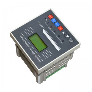
3.Function Operation Instructions
1)The button layout of the fire equipment power status monitoring host is as shown in the figure below:

2)Button function and instruction
① Reset:
After device reset is completed, all states of the system are reinitialized. (This function can be operated under the login state)
②Self-inspection:
Complete the self-test of the device. The self-test content includes: fault sound, alarm sound, indicator light, printer, etc.
③ Muffling:
When the device detects a fault message or an alarm message, it will be accompanied by a corresponding fault or alarm sound. This key can temporarily eliminate the sound, but if there is a new fault or alarm message after the sound is muted, the sound will restart.
④Function:
Switch the display window, view and set the parameters of each window
⑤ Login, logout:
When you are not logged in, press the login and logout keys, and the cursor will flicker in the unlogged area at the bottom of the window. At this time, enter the 8888 password-login is successful, and press the login and logout keys again to log out.
⑥ OK, print key:
It is used to confirm or save when logging into the system and setting parameters. In addition, it is also used as manual printing when there is a fault page.
⑦Other keys:
Numeric keys or up, down, left, right (cursor) positioning keys.
Installation Notes
1)Engineering Wiring Requirements
① A monitoring device can be connected with at most (such as 32* loop number) detectors, and the loop number is ≤16; the specific models are: 32*/64*/128*/256*
② The communication line between the monitoring equipment and the detector should be a twisted pair, and the wire diameter should not be less than 1.5mm2. The longest laying distance of the communication line should be less than 1200m. If the use distance of the communication line exceeds 1200m, a repeater should be added. When the system is applied in a place with strong interference, the communication line should use shielded twisted pair;
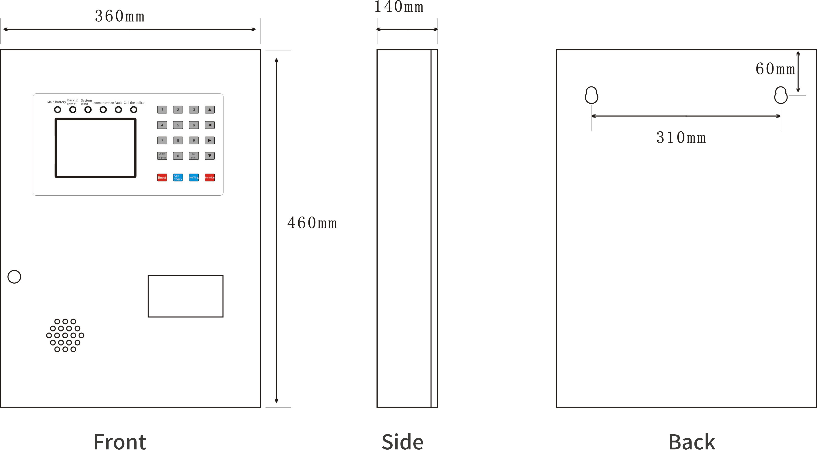
2)Dimensional drawing:
3)Wiring Instructions:

N、L: AC 220V power input
:Chassis ground, connected to the earth
NC: is a blank terminal
KA, KB: Control output (normally open contact, capacity AC250V/5A)
S+1, S-1: 1 loop two bus communication interface (communication with the sensor)
S+2, S-2: 2-loop two-bus communication interface (communication with the sensor)
S+3, S-3: 3-loop two-bus communication interface (communication with the sensor)
S+4, S-4: 4-loop two-bus communication interface (communication with the sensor)
Note: Because the configuration of the device is different, the wiring terminals may be different, the actual object shall prevail
|
product name |
product model |
basic function |
remarks |
|
|
Fire power mainframe |
NLK999 |
|
Manage and monitor each sensors and extension |
wall mounting type 600mm*150mm*500mm |
Related products
-
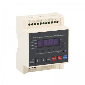
Single-channel electrical fire monitor
Basic functions The type electrical fire monitoring detector can realize real-time monitoring and collection of the residual current and temperature value of the controlled circuit, and will send out an audible and visual fault alarm signal when the fault alarm data of the detection circuit is collected; it can also be networked with the electrical fire monitoring host, and the monitoring host can Judging the state of the on-site detectors, the host computer analyzes and processes to indicate...
-
Combined Electrical Fire Monitor
Shape and installation dimensions Product information Product model: NLK888DDS Rated operating current IN (A): 16A~1600A Rated working voltage UE (V): AC220V Residual current warning and alarm value: 20mA~1000mA can be set arbitrarily Three-phase current warning and alarm value: no Temperature warning and alarm value: 20°C~150°C can be set arbitrarily Number of leakage circuits: 1~16 circuits Number of temperature loops: 1~8 loops Alarm protection: protection or no protection can be set Pro...
-
Electricalfirebuilt-in
Basic function The electrical fire monitoring detector can realize real-time monitoring and collection of the residual current and temperature value of the controlled circuit, and will send out an audible and visual fault alarm signal when the fault alarm data of the detection circuit is collected; it can also be networked with the electrical fire monitoring host, and the monitoring host can judge The state of the on-site detector, the host computer analyzes and processes to indicate the type...
-
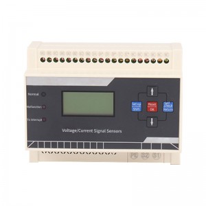
Fire power supply
Basic skills The voltage/current signal sensor can collect the voltage and current value of the detection circuit at the same time, or only collect a certain circuit or a few channels according to actual requirements. It can be networked with the fire-fighting equipment power monitoring host, and the monitoring host can judge the status of the on-site sensor. Status, after the host computer analyzes and processes, it indicates the type of a circuit fault alarm, and sends out an audible and vi...
-

Electrical fire host computer
Overview The electrical fire monitoring system is a computer measurement and control system that integrates alarm, monitoring, control and management functions, which is independently developed in response to the sharp increase in domestic electrical fires in recent years. The system has intuitive interface, strong usability, reasonable structure, high reliability, strong function and convenient maintenance. The system can be widely used in the centralized management of power consumption and ...


